Abstract
Four springs, with k values of 930 Nm-1, 712 Nm-1, 1620 Nm-1 and 330 Nm-1 were constructed, using copper and steel. Values for the spring constants were predicted based on various properties of the springs (wire and spring diameter, shear modulus, and number of turns). These predicted values of k varied from the real values by as much as 620 Nm-1. However, this was still within the error margins (±637 Nm-1 in the extreme case).
1. Introduction
The aim of this experiment was to design, construct, and study springs having specified spring constants (k), basing the design on formula 1, and the study on formula 2.
| k = | G d4
8 n D3 |
| k = | F
Dx |
Variables
| k | is the spring constant |
| G | is the shear modulus of the wire |
| d | is the diameter of the wire |
| n | is the number of turns in the spring |
| D | is the diameter of the spring |
| F | is the force applied to the spring |
| Dx | is the extension in the spring |
Mechanical springs are elastic bodies, in that when a load is applied, they change shape to the absorb energy, and importantly when the load is removed, the original shape is recovered.
Within the elastic region, the relationship between load and extension is usually linear. This is known as Hooke's Law.
Research suggested that the ratio of the diameter of the spring to the diameter of the wire (the D:d ratio) should be within the range of 4-13, optimally between 7 and 10 (Spring Research Organisation (1974:9), Harold Carlson (1978:197)). For high values of k, the D:d ratio should be low.
Note that it is by approximating helical springs to straight bars in pure torsion that equation 1 is derived. The formula is therefore inaccurate at low D:d ratios, since the derivation ignores any effects caused by bar curvature and direct shear loading.
2. Method
2.1 Special Apparatus
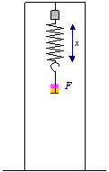
▶ Figure 1. Custom designed frame for finding k of compression springs by measuring the change in length caused by adding masses.
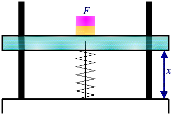
▲ Figure 2. Frame when used to measure the extension of the springs.
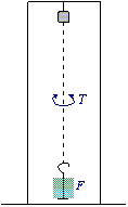
▼ Figure 3. Frame when set up as a torsion balance to measure G.
Several distinct pieces of apparatus help in the creation and analysis of springs, some of which are shown above and to the left.
The value of k for the commercial springs was found using a custom built frame (see figure 1) designed to apply a measurable force to springs, thus compressing them. (All commercial springs that were studied were compression springs.) The frame allowed F and Dx to be measured, the value of k being determined using equation 2.
For tension springs (i.e. all the constructed springs), another frame was used. This setup is shown in figure 2. Again, F and Dx were measured, and k was calculated using equation 2.
The value of G could have been found in tables, however, since the exact consistency of the wires used were not known, it was decided that measuring the actual G would be more suitable.
Note 1: Shear Modulus
A full treatment of this technique is out of scope for this report, but can be found in most standard text books.
To find G, a torsion balance was used (see figure 3). By measuring the time taken for N torsional oscillations of a length of wire first with a mass M1 and then with a mass M1+M2 attached, the shear modulus G can be found.
Other values were measured using standard laboratory equipment.
To actually wind the springs, a coiling machine was used. This is a piece of apparatus that simply rotates a rod around which can be wrapped wire. It is not designed for making springs (research indicates that its primary function is probably winding electromagnet coils), but it was surprisingly effective nonetheless.
2.2 Techniques
Cold Drawing
Cold drawing is a technique for straightening wire. The wire is clamped at one end, and a steady force is applied, creating a large tension which removes any coiling that may have been caused during storage.
2.3 Design and Construction
For each spring constructed, the steps below were followed.
- A material was selected. Materials were selected based on three primary criteria: thickness (d), strength (G), and the tendency to stay wrapped after winding. (Some steels were relatively dangerous in this regard, viciously uncoiling the instant they were released.)
- A 0.8m length of wire was cut off and straightened by cold drawing.
- This straight wire was then fixed into the tall frame (Figure 3).
- A known mass M1 was hooked to the bottom of the wire.
- The time for N torsions was measured.
- Another known mass M2 was hooked to the bottom of the wire, bringing the total mass to M1+M2.
- The time for N torsions was again measured.
- The value of G was calculated using the equation in Note 1. This value is for comparison only.
- The value of d (the diameter of the wire) was then measured using a micrometer.
- By multiplying d by the d:D ratio selected, the optimal value of D was found. (A bigger d:D ratio results in a smaller k, so the minimum d:D ratio of 7 was used. See the introduction.)
- Some studding or core with a diameter close to the required value of D was found.
- The spring was wound for as many turns as were deemed suitable. Too few turns and the spring is difficult to use, too many and limitations in the winding machine became evident (like the core or studding not being long enough!).
- The real value of D was found. (i.e., the diameter of a spring wound on the selected studding was found.)
- The spring was fixed into the frame as shown in Figure 2.
- The length of the spring with no mass attached was measured.
- At this stage, a set of data points were collected to enable
k to be found. This involved two simple stages, repeated
until the spring deformed:
- A known mass was attached to the spring.
- The new length was measured.
3. Results
3.1 Constructed Springs
The data for each spring that was constructed during the course of this experiment is as follows:
| Property | Variable | Units | Insulated Copper | Bare Copper | Bare Copper | Steel |
|---|---|---|---|---|---|---|
| Wire Diameter | d | m | 0.00153 | 0.00117 | 0.00203 | 0.00069 |
| Wire Length | L | m | 0.68400 | 0.75000 | 0.66800 | 0.74000 |
| Number of Swings | N | 10 | 10 | 10 | 10 | |
| Mass 1 | M1 | kg | 2.0955 | 2.0955 | 2.0955 | 2.0955 |
| Mass 2 | M2 | kg | 2.0448 | 2.0448 | 2.0448 | 2.0448 |
| Time with 1 mass | T1 | s | 19.05 | 30.55 | 10.67 | 63.79 |
| Time with 2 masses | T2 | s | 26.95 | 43.14 | 15.23 | 90.78 |
| Mass Radii | R | m | 0.0513075 | 0.0513075 | 0.0513075 | 0.0513075 |
| Shear Modulus | G | Pa | 37.6×10⁹ | 47.3×10⁹ | 36.5×10⁹ | 85.7×10⁹ |
| Ideal Diameter | D″ | m | 0.01071 | 0.00819 | 0.01421 | 0.00483 |
| Studding Diameter | D′ | m | 0.00991 | 0.00784 | 0.01589 | ? |
| Spring Diameter | D | m | 0.01300 | 0.00978 | 0.01914 | 0.00724 |
| Number of Turns | n | 23 | 28 | 11 | 28 | |
| Predicted Spring Constant | k′ | Nm-1 | 510.2 | 422.7 | 1004.4 | 228.6 |
| Actual Spring Constant | k | Nm-1 | 930.3 | 712.4 | 1618.0 | 330.2 |
| Maximum Load | Fmax | N | ? | 6.5 | 25 | 23 |
3.2 Sources of Error
- Masses: DM = ± 0.05×10⁻³kg
-
The balances used were accurate to a tenth of a gram.
- Mass Radii: DR = ± 0.11×10⁻³m
-
The error for one reading of the radius of the masses was ± 0.53×10⁻³m, however 6 readings were taken and averaged, reducing the error by a factor of √6.
- Times: DT = ± 0.1s
-
This error is down to reaction time, as the time measurements were performed with a stop watch.
- Wire Diameter: Dd: ± 0.25×10⁻³m
-
This quite considerable error is due to:
- Irregularities in the wire.
- Defects caused by cold drawing.
- The ductability of the wire and the variations in the pressure applied to the micrometer (By varying the pressure on the micrometer, different diameters are measured, within a range of ± 0.25×10⁻³m).
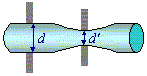
▲ Figure 4. Exaggerated diagram to show how, when too much pressure is applied to the micrometer, the wrong diameter may be measured.
It is ironic that the micrometer, with its 1×10⁻⁵m (10 micron) accuracy, would be the main source of error for the wire diameter, but when using a hand held micrometer is it nigh on impossible to always apply the same pressure.
- Spring Diameter
-
- Commercial Springs: DD = ± 0.06×10⁻³m
-
The error in the diameter of commercial springs is caused by the same problems as the error in the wire diameter d, but since commercial springs use considerably more rigid material, the error is not very pronounced.
- Constructed Springs: DD = ± 4×10⁻³kg
-
The error in the measurement of the diameter of constructed springs is by far the largest error of the entire experiment. It is due largely to defects in the construction process used, such as the wire loosening during construction, the wire wrapping over itself, or irregularities during the winding of the spring.
It would unfortunately have been difficult to achieve better results using the time and equipment available.
- Wire Length: DL = ± 2×10⁻³m
-
This error is due to the difficulty of measuring long lengths, vertically, with the wire clamped into a frame.
The obvious solution to this problem, measuring the wire horizontally, requires that the wire be marked (or cut) at the points where it is clamped, which introduces a greater error than the measuring actually involves.
- Spring Length
-
- Commercial Springs: DDx = ± 2×10⁻³m
-
This is a large error, which is caused by inherent inaccuracies of the equipment used. The actual error was reduced considerably by using multiple measurements for each spring tested.
- Constructed Springs: DDx = ± 1.2×10⁻³kg
-
This is again a considerable error. It is caused by the difficulty in measuring the length of the spring while it is hanging in the frame with masses attached (see figure 2). The main problem is related to that described under the d error: it is difficult to gauge the pressure applied to the micrometer. In the case of spring length, the problem is even more pronounced as the length of the spring can be changed inadvertently by considerably larger amounts.
Once again, the error was reduced dramatically by taking multiple measurements and finding the mean.
3.3. Agreement of predicted and measured values of k
An important part of this investigation was to compare the predicted and measured values of k. To do so, we must first establish the error in k′, the predicted value.
k′ may be calculated using formula 3.
Note 2: Derivation
Formula 3 is derived from substituting an expression for G into equation 1. See note 1.
| k′ = | 4 π L N2 R2 (M1 + M2)
D3 n (T22 + T12) |
Using the method of partial differentiation, an expression for Dk′ may be derived. It is shown in formula 4.
| Dk′ = | 4 π L N2 R2 (M1 + M2)
D3 n (T22 + T12) |
( |
DL
L |
+ |
2DR
R |
+ |
3DD
D |
+ | ||||||
|
||||||||||||||
The error margins that this formula yields for the calculated value of d′ for each spring are shown in table 2.
▼ Table 2. Predicted and measured values of k for the constructed springs.
| Spring | / Nm-1 |
/ Nm-1 |
/ Nm-1 |
|---|---|---|---|
| Insulated Copper | 510 | ±475 | 930 |
| Thin Copper | 422 | ±522 | 712 |
| Thick Copper | 1004 | ±637 | 1618 |
| Steel | 228 | ±381 | 330 |
The errors in the k values were found during the regression analysis of the load/extension data used to find the values of k themselves. These errors were negligible (of the order of one part per million). This is because the values of k were derived from multiple data points and the error in F is minuscule.
As can be seen from the table, the measured values of k fall within the error margins for k′. This indicates that the equations do indeed apply to the constructed springs.
4. Discussion
4.1 Analysis of Extension of Constructed Springs
Chart 1 shows the graphs used to find the value of the spring constant k for each constructed spring. The lines are the lines of best fit for the first part of the curves, the elastic deformation stage of the springs' extensions, before they plastically deform and no longer return to their original length.
There was (probably) an error in the measurement of the initial length of the steel spring, which would explain why the data forms a straight line, but does not going through the origin. (It is expected that the lines would go through the origin, as this corresponds to zero extension for zero load.)
In the case of this thin bare copper, the elastic limit (maximum load point) is clearly visible, as the line curves after 6.5N. For the other springs, the elastic limit was found by simply adding then removing masses until the length with no load changed, without recording the extension for the loads up to that point. This is why the curves for the other springs cannot be seen on the graphs.
4.2 Commercial Springs
Two commercial springs were examined, as a set of controls for the constructed springs. They were deemed to have been made of stainless steel, and a value of G of 83.9 GPa was found in tables.
As can be seen from chart 2, the commercial springs are much stronger than the constructed versions. Values of k, found from the gradients of the lines shown, were 5073Nm-1 and 4152m-1. This strength relative to the constructed springs is mainly due to the materials used; the commercial springs tested appeared to be made of stainless steel, which was not available, and is in any case very difficult to wind by hand.
A brief analysis of the ratio of the diameters of the springs to the diameters of the wire for a dozen commercial springs confirmed the suggestions found in Spring Research Organisation, 1974:9 and Harold Carlson, 1978:197 for D:d ratios. Values ranged from 5 to 8, with a mean of 7.
Improvements
Had more materials, more wire diameters, and more of the ever elusive time been available, many more springs could have been constructed and tested.
With experience of the winding process, the springs would have presumably become of greater and greater quality, thus reducing the error in D which made the predictions so inaccurate.
5. Conclusion
It was established that equations 1 and 2, shown below, did indeed apply to hand-built springs, within the margin of error.
| k = | G d4
8 n D3 |
| k = | F
Dx |
The four springs where made with k values of 930 Nm-1, 712 Nm-1, 1620 Nm-1 and 330 Nm-1 and using copper and steel. The predicted values for the spring constants were based on various properties of the springs, namely the wire and spring diameters, the shear modulus of the wire, and the number of turns in the spring. The predicted values of k varied from the real values by as much as 620 Nm-1, but were still within the error margins as these were large, ranging from ±381 Nm-1 to ±637 Nm-1.
The main limitation was the quality of the constructed springs. A professional spring winding machine would have facilitated fabrication (for example, see Harold Carlson (1978:243)). This would have allowed for much closer agreement of the predicted and measured values of k.
References
Spring Research Organisation (1974). Helical Springs. Oxford: Oxford University Press. Engineering Design Guides.
Harold Carlson (1978). Spring Designer's Handbook. New York: Marcel Dekker, Inc.